
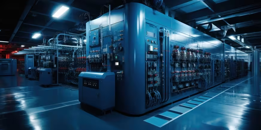
Uninterruptible Power Supply (UPS) Systems
Perfect Solution Contracting provides integrated Uninterruptible Power Supply (UPS) solutions designed to support continuity of electrical power for critical and sensitive loads in data centers, commercial buildings, industrial facilities, infrastructure projects, utilities, and other critical facilities.
A UPS system provides an immediate source of power to connected loads when the normal electrical supply is interrupted or experiences conditions outside the acceptable operating limits of the selected system.
Depending on the system design, stored energy from the battery system supports the connected load during the transition period until the normal supply is restored, an alternative source such as a diesel generator becomes available, or an orderly shutdown is completed.
Our scope can include engineering coordination, technical and material submittals, equipment supply, installation, power and control cabling, batteries, earthing, system interfaces, testing, commissioning, and final handover according to approved project requirements.
Online Double-Conversion UPS
For critical applications, Online Double-Conversion UPS systems can be provided where this topology is required by the approved electrical design and load characteristics.
During normal operation, the rectifier converts the incoming AC power to DC power to support the DC bus and battery charging functions according to the system design.
The inverter converts DC power into regulated AC output power for the connected critical loads within the operating characteristics of the selected UPS system.
When the normal input source is lost, the inverter can continue supplying the load using stored battery energy for the available autonomy period, subject to battery capacity, condition, load, and system configuration.
Rectifier / Charger
The Rectifier / Charger is a principal component of many Online UPS systems. It converts incoming AC power into DC power and supports battery charging and the UPS DC bus according to the manufacturer's system architecture.
Selection and configuration are coordinated with the incoming power characteristics, UPS rating, battery capacity, required autonomy, charging requirements, environmental conditions, and project specifications.
Inverter
The inverter converts power from the UPS DC bus into AC output power suitable for the connected loads at the required voltage and frequency within the specified system operating limits.
Inverter and UPS capacity are selected according to actual load requirements, load characteristics, required capacity margins, future expansion where specified, and the required redundancy architecture.
Static Bypass
UPS systems can incorporate a Static Bypass path that allows the connected load to be transferred to an available bypass source under defined operating conditions.
Static bypass operation can be used during certain overload conditions, inverter faults, or other operating conditions according to the design and settings of the selected UPS.
Successful transfer depends on the condition of the bypass source, acceptable voltage and frequency limits, synchronization conditions, and the specific characteristics of the UPS system.
The static bypass should therefore not be considered an independent backup power source by itself. Its availability depends on the electrical source feeding the bypass path.
Maintenance Bypass
A Maintenance Bypass arrangement can be provided to allow the UPS equipment to be isolated for maintenance while maintaining a direct power path to the load when permitted by the system architecture and operating procedure.
The maintenance bypass can be incorporated within the UPS system or provided through a separate external bypass panel depending on system capacity, configuration, manufacturer design, and project requirements.
Transfer and isolation procedures should follow the approved sequence of operation and manufacturer instructions to avoid incorrect switching or unintended interruption of the connected loads.
UPS Capacity & Sizing
UPS capacity is selected according to the actual critical load requirements rather than solely from the sum of equipment nameplate ratings.
UPS systems are commonly rated in both kVA and kW. Both ratings should be verified when comparing the connected load with the available UPS capacity.
Sizing considerations include actual load power, power factor, load characteristics, inrush conditions, future expansion where specified, redundancy, environmental conditions, and the facility's operating philosophy.
The selected UPS should also be coordinated with the characteristics of electronic and nonlinear loads connected to the system.
Battery Systems
The battery system provides stored energy for the UPS during loss of the normal source or during the transition to another approved power source.
Battery capacity is determined according to UPS load, required runtime or autonomy, DC bus voltage, battery characteristics, manufacturer requirements, and the approved system design.
Required battery capacity can also be affected by temperature, discharge rate, battery aging, design margins, and end-of-life performance requirements where these criteria are specified.
Different battery technologies can be used depending on the selected UPS architecture, application, operating environment, maintenance strategy, and approved project requirements.
Battery Cabinets & Racks
Batteries can be installed in dedicated battery cabinets, battery racks, or battery rooms depending on system capacity, battery technology, equipment arrangement, and project requirements.
Installation coordination considers maintenance clearances, ventilation, environmental conditions, electrical protection, cable routing, equipment access, and manufacturer requirements.
Battery Runtime & Autonomy
UPS runtime is not a fixed value. Actual battery autonomy depends on the connected load, available battery capacity, battery condition, temperature, discharge characteristics, and system configuration.
The system can be designed for a specified autonomy period according to project requirements, whether the objective is to bridge the time required for generator startup or to support the critical load for a longer defined period.
Redundancy & Availability
Applications requiring higher levels of power continuity can use redundant UPS configurations such as N+1 or other parallel architectures where specified by the approved design.
Installing multiple UPS units does not automatically create complete system redundancy. Available capacity after the loss of a unit, bypass architecture, batteries, distribution paths, and common points of failure should also be considered.
Modular UPS Systems
Modular UPS systems can be used where their architecture is appropriate for the project. These systems can incorporate multiple power modules within a coordinated UPS platform.
Depending on the selected product architecture, modular systems can support capacity expansion or redundancy requirements. The number of modules and required capacity are determined by the actual load and system philosophy.
UPS & Generator Compatibility
Where a UPS system operates from a standby diesel generator, the characteristics of both systems should be coordinated to support stable operation when the generator becomes the upstream source.
Coordination can include generator capacity, voltage and frequency response, UPS input characteristics, rectifier behavior, generator loading, load sequencing, and bypass-source acceptance settings.
Compatibility should be reviewed as part of the electrical system design rather than assuming that every UPS and generator combination will operate satisfactorily without engineering coordination.
Harmonics & Input Power Factor
UPS input characteristics such as power factor and Total Harmonic Distortion of current (THDi) should be reviewed when coordinating the UPS with the upstream utility supply, transformers, generators, cables, and switchgear.
Actual performance values depend on UPS technology, loading conditions, system configuration, and the selected product. Approved manufacturer data should therefore be used for detailed electrical coordination.
Electrical Connections
UPS input and output connections are coordinated with distribution boards, circuit breakers, power cables, bypass sources, and critical-load distribution panels according to the approved electrical design.
Power cable sizing considers current-carrying capacity, installation method, ambient temperature, grouping, voltage drop, short-circuit withstand, and applicable correction factors.
Battery and DC cables are coordinated with operating current, prospective fault conditions, protection requirements, route length, voltage drop where relevant, and manufacturer recommendations.
Electrical Protection
Protective devices upstream and downstream of the UPS are coordinated with system characteristics, short-circuit conditions, bypass paths, and the required protection and selectivity philosophy.
The available fault current from the UPS inverter can differ from the fault current available when the load is supplied through the bypass source. Protection coordination should therefore consider the applicable UPS operating modes.
Earthing & Neutral Arrangement
UPS equipment, enclosures, battery cabinets, racks, and associated metallic components are bonded to the facility earthing system according to the approved electrical design.
Neutral and earthing arrangements depend on the UPS architecture, upstream and bypass sources, transformers where used, transfer arrangements, and the project's grounding philosophy.
Neutral-to-earth bonding should therefore be provided only at the locations defined by the approved electrical system design.
UPS & Battery Room Coordination
UPS equipment and batteries require suitable installation conditions including temperature, ventilation, maintenance clearances, equipment access, and environmental conditions.
Temperature is particularly important for many battery technologies because it can affect battery performance and service life. Cooling and ventilation requirements are coordinated with the selected equipment and manufacturer recommendations.
Equipment weight, battery weight, floor loading, installation routes, replacement access, and maintenance requirements should also be coordinated with the architectural, structural, and mechanical design.
Monitoring & Communications
Modern UPS systems can provide monitoring of input and output conditions, battery status, bypass status, alarms, loading, and other operating parameters supported by the selected controller.
Where specified, the UPS can interface with the Building Management System (BMS), Electrical Power Monitoring System (EPMS), or SCADA platform.
Integration points can include UPS status, battery status, common alarm, bypass status, load level, electrical measurements, and other information supported by the selected system and approved points list.
Technical Submittals & Drawings
Before procurement, technical documentation can include UPS data sheets, kVA / kW ratings, efficiency information, input and output characteristics, battery data, autonomy calculations, dimensions, weights, environmental requirements, communication interfaces, and protection information.
Coordination documentation can include Single Line Diagrams (SLD), General Arrangement (GA) drawings, battery arrangements, cable routes, bypass panel arrangements, equipment schedules, and cable schedules.
Factory Acceptance Testing
Where required by the project, Factory Acceptance Testing (FAT) can be performed to verify UPS configuration and specified operating functions before delivery.
FAT can include verification of input and output operation, rectifier and inverter functions, static bypass operation, alarms, protection, interfaces, and specified load tests according to the approved Inspection and Test Plan (ITP).
Installation & Pre-Commissioning
Following delivery, the UPS equipment, batteries, and accessories are inspected for transportation condition, completeness, equipment identification, and visible damage before installation and commissioning.
Installation can include UPS positioning, input and output power cables, bypass connections, battery cables, earthing, control wiring, communications, and interfaces with associated electrical systems.
Pre-commissioning checks can include verification of electrical connections, phase sequence where applicable, earthing, battery connections, protective devices, system settings, alarms, and bypass arrangements according to the approved commissioning procedure.
Functional Testing & Commissioning
Functional testing verifies normal UPS operation, transition to stored energy following loss of the normal source, restoration of the normal source, alarms, protection, and other specified functions.
Static bypass and maintenance bypass functions are tested according to the system configuration, manufacturer's procedures, and approved sequence of operation.
Where required, controlled load testing can be performed to verify UPS and battery performance at specified load conditions.
A battery runtime test can also be performed where specified, with the test load, operating conditions, duration, and acceptance criteria defined by the approved commissioning procedure and project requirements.
Where required, Site Acceptance Testing (SAT) can verify the complete installed UPS system and its interfaces with incoming supplies, batteries, bypass arrangements, critical-load distribution, and monitoring systems.
Standards & Project Requirements
UPS systems are selected, installed, and tested according to the approved project specifications, manufacturer requirements, and relevant standards applicable to the selected equipment and system.
Depending on the UPS type and project requirements, relevant standards can include the IEC 62040 series for Uninterruptible Power Systems, together with other applicable project-specific requirements.
Perfect Solution Contracting provides complete UPS solutions covering engineering coordination, technical submittals, procurement, installation, battery systems, power and control cabling, bypass arrangements, earthing, system integration, FAT/SAT support where required, testing, commissioning, and final handover.
- Uninterruptible Power Supply (UPS) systems.
- Online Double-Conversion UPS systems.
- Rectifier / Charger.
- Inverter.
- DC bus systems.
- Static Bypass.
- Maintenance Bypass.
- UPS kVA / kW sizing.
- Battery systems.
- Battery cabinets and racks.
- Runtime and autonomy calculations.
- N+1 redundancy where required.
- Modular UPS systems where specified.
- UPS and diesel-generator coordination.
- Input power factor and THDi coordination.
- UPS input and output cabling.
- Battery DC cabling.
- Circuit-breaker and protection coordination.
- Earthing and bonding.
- Neutral and grounding coordination.
- UPS and battery-room cooling and ventilation coordination.
- BMS / EPMS / SCADA integration where specified.
- Single Line Diagrams (SLD).
- General Arrangement (GA) drawings.
- Factory Acceptance Testing (FAT) where required.
- Site Acceptance Testing (SAT) where required.
- Static Bypass testing.
- Maintenance Bypass testing.
- Battery runtime testing where required.
- Controlled load and performance testing.
- Testing, commissioning, and final handover.