
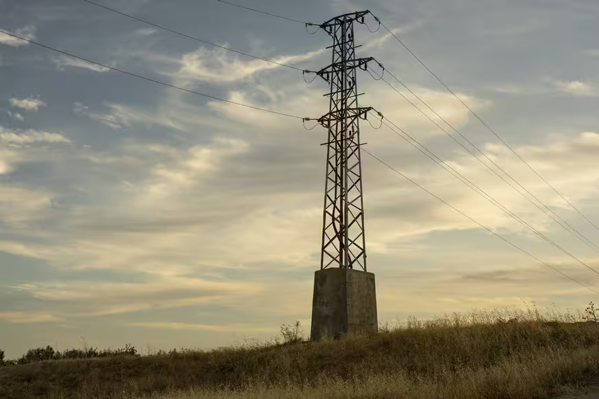
Earthing & Lightning Protection Systems
Perfect Solution Contracting provides comprehensive earthing, electrical bonding, and lightning protection solutions for commercial buildings, industrial facilities, infrastructure projects, utilities, and electrical installations.
Our scope can include engineering coordination, technical and material submittals, supply, installation, bonding, inspection, testing, measurement, documentation, and final handover in accordance with approved project drawings, specifications, and system requirements.
The works can include earthing of electrical equipment, distribution boards, transformers, medium-voltage and low-voltage switchgear, communication and low-current systems where required, cable containment systems, metallic services, and external lightning protection systems.
Electrical Earthing Systems
An electrical earthing system provides the required connection to earth for designated conductive parts according to the electrical system design, protection philosophy, and applicable project requirements.
The earthing arrangement is coordinated with the power distribution system, protective devices, neutral arrangement, electrical equipment, metallic parts, and other building services according to the approved design.
Main Earthing Network
The main earthing network can include earthing conductors, earth electrodes, earth rods, inspection pits, test points, connections, main earth bars, and other components required by the approved earthing design.
The quantity, arrangement, type, and location of earth electrodes and conductors are determined according to the electrical design, soil conditions, project requirements, and the specified earth resistance criteria.
Earth Electrodes & Earth Rods
Earth electrodes provide an electrical connection between the earthing system and the ground. Different electrode arrangements can be used depending on site conditions and the approved earthing design.
Solutions can include driven earth rods, buried conductors, ring earth electrodes, earthing grids, or other approved arrangements suitable for the project and soil conditions.
Electrical Equipment Earthing
Equipment earthing includes connecting exposed conductive parts of electrical equipment to the protective earthing system in accordance with the approved design and electrical protection requirements.
This can include distribution panels, electrical equipment, motors, UPS systems, generators, mechanical equipment with electrical supplies, and other equipment requiring protective earthing.
Low Voltage Switchgear Earthing
Low-voltage switchgear, Main Distribution Boards (MDBs), Sub-Main Distribution Boards (SMDBs), and Distribution Boards (DBs) are connected to the earthing system according to the approved electrical drawings and equipment requirements.
The work can include bonding of the enclosure, internal earth bar, protective conductors, doors or removable metallic parts where required, and other designated earthing points.
Medium Voltage System Earthing
Medium Voltage (MV) equipment requires careful coordination of the earthing system with the electrical protection philosophy and overall power distribution design.
The scope can include earthing of MV switchgear, earthing switches, cable screens or metallic sheaths as applicable, associated equipment, and Ring Main Units (RMUs) according to the equipment configuration and approved design.
Transformer Earthing
Transformer earthing is coordinated with the transformer type, distribution system, neutral arrangement, protection requirements, and approved electrical design.
The work can include earthing of the transformer enclosure, exposed metallic components, neutral point where applicable, and connection to the main earthing network according to the approved system arrangement.
Generator Earthing
Diesel generator earthing is coordinated with the standby power configuration, Automatic Transfer Switch (ATS), neutral arrangement, protection philosophy, and the building earthing system.
Generator neutral earthing and bonding arrangements can vary according to the system configuration and transfer arrangement. Installation is therefore carried out according to the approved electrical design and equipment requirements.
Cable Tray & Raceway Earthing
Cable trays, cable ladders, metallic trunking, metallic conduits, and other conductive cable containment systems can be bonded to the earthing system where required by the project design.
Electrical continuity across sections and joints is verified, with additional bonding conductors or jumpers provided where required by the approved installation details.
Equipotential Bonding
Equipotential bonding connects designated conductive parts and services to the earthing system according to the electrical design and project requirements.
Bonding can include structural metallic elements, mechanical services, metallic piping, cable containment, and other conductive services identified by the approved design.
Telecommunications & Low-Current Earthing
Telecommunications, information technology, and low-current systems may require specific earthing and bonding arrangements according to equipment requirements and the project design.
These arrangements are coordinated with the building's overall earthing and bonding system and equipment manufacturer requirements to avoid inappropriate isolated earthing arrangements or unintended potential differences.
Lightning Protection Systems
A Lightning Protection System (LPS) is designed to intercept direct lightning strikes and provide a controlled path for lightning current toward earth, according to the approved lightning protection design.
A conventional external lightning protection system generally includes an air-termination system, down-conductor system, earth-termination system, bonding provisions, test points, and associated components required by the design.
Air-Termination System
The air-termination system can include air rods, conductors, or mesh arrangements positioned according to the approved lightning protection design.
The arrangement and locations are coordinated with the building geometry, height, roof configuration, exposed elements, and the protection methodology selected for the project.
Down Conductors
Down conductors provide conductive paths between the air-termination system and the earth-termination system according to the approved lightning protection design.
Their routes, supports, connection points, and coordination with architectural, structural, and MEP services are considered during installation.
Lightning Protection Test Points
Test joints or test points can be provided at designated locations to support inspection, measurement, and maintenance of the lightning protection system.
These points are positioned according to the approved design and should remain accessible for inspection and testing where required.
Lightning Protection Earthing
The lightning protection earth-termination arrangement is coordinated with the building's overall earthing system according to the approved design and bonding requirements.
The final arrangement depends on the electrical earthing design and lightning protection concept. Lightning protection earthing should therefore not be treated automatically as a completely independent earthing network without considering the overall bonding design.
Surge Protective Devices (SPD)
Surge Protective Devices (SPDs) perform a different function from the external lightning protection system. SPDs can form part of the internal protection strategy against transient overvoltages where required by the electrical design.
SPD type, rating, coordination, and installation location are selected according to the electrical distribution system, protection concept, earthing arrangement, connected equipment, and project requirements.
Coordination with Electrical Systems
Earthing systems require coordination with medium- and low-voltage switchgear, transformers, generators, UPS systems, battery systems, Motor Control Centers (MCCs), and other electrical equipment.
This coordination helps maintain consistency between the earthing arrangement, electrical protection philosophy, distribution architecture, and approved project drawings.
Civil & Structural Coordination
Earthing and lightning protection works require early coordination with civil and structural works, particularly for buried conductors, earth electrodes, inspection pits, foundation-related earthing components, embedded conductors, and connection points.
Coordination before concrete works, backfilling, and final finishes helps ensure that buried components and required access points are installed in their approved locations.
Architectural Coordination
Visible lightning protection components are coordinated with roofs, façades, architectural finishes, and external building elements while maintaining the required protection arrangement.
This can include air terminals, roof conductors, down conductors, test joints, supports, clamps, and other visible components of the system.
Earth Pits & Inspection Pits
Earth pits or inspection pits can be provided at designated locations to allow access to earth electrodes, connections, and testing points.
Pit type, cover, location, mechanical protection, and finish are coordinated with the surrounding area and project requirements.
Earthing Conductors & Accessories
Earthing materials can include conductors, earth rods, earth bars, clamps, connectors, test points, inspection pits, bonding conductors, and other accessories required to complete the system.
Material type, conductor size, connection method, and installation arrangement are selected according to the approved design, environmental conditions, and project specifications.
Buried Earthing Connections
Buried earthing connections require connection methods suitable for the materials, installation environment, and approved project requirements.
Approved connection methods such as exothermic welding can be used where specified by the project design or technical requirements.
Earth Resistance Testing
Following installation, the required measurements can be carried out to verify the performance of the earthing system and compare measured results with the project-specific design criteria.
Earth resistance measurements are documented in testing records and submitted as part of the project inspection and handover documentation where required.
Electrical Continuity Testing
Continuity testing can be performed to verify the electrical connection between equipment, conductive parts, bonding points, protective conductors, and the earthing network.
Testing is performed at the applicable locations identified within the approved inspection and testing requirements.
Lightning Protection System Inspection
Lightning protection inspection can include verification of the air-termination network, down conductors, test points, connections, supports, bonding, and earth-termination system against approved drawings and installation details.
Inspection and measurement results can be recorded as part of testing, commissioning, and final handover documentation.
Technical & Material Submittals
Technical submittals can include earthing conductors, earth electrodes, earth rods, earth bars, clamps, connectors, inspection pits, test joints, lightning protection components, and other proposed materials.
Submittals are coordinated with the approved drawings, specifications, system design, and materials proposed for installation.
Shop Drawings
Shop drawings can identify the earthing network, electrode locations, inspection pits, conductor routes, bonding points, equipment earthing, air-termination network, down conductors, and lightning protection test points.
Drawings are coordinated with electrical, structural, architectural, mechanical, and other building services before installation.
Testing & Commissioning
Inspection and testing activities are performed according to the system type, approved procedures, project requirements, and installed equipment.
Activities can include visual inspection, connection verification, continuity testing, earth resistance measurement, bonding verification, lightning protection system inspection, and documentation of test results.
Documentation & Final Handover
Final handover documentation can include approved technical submittals, inspection records, test reports, earth resistance measurements, material documentation, and As-Built drawings according to project requirements.
Perfect Solution Contracting provides earthing and lightning protection works as part of integrated electrical solutions, from engineering coordination and material supply through installation, testing, documentation, and final handover.
Our Earthing & Lightning Protection Scope
- Main earthing networks
- Earth electrodes and earth rods
- Buried earthing conductors and grids
- Earth pits and inspection pits
- Electrical equipment earthing
- Low-voltage switchgear earthing
- Medium-voltage switchgear earthing
- RMU earthing
- Transformer earthing
- Generator earthing
- UPS system earthing
- Cable tray and raceway bonding
- Equipotential bonding
- Telecommunications and low-current earthing
- Lightning Protection Systems (LPS)
- Air-termination systems
- Down conductors
- Lightning protection test points
- SPD coordination
- Exothermic welding where specified
- Electrical continuity testing
- Earth resistance testing
- Lightning protection system inspection
- Technical and material submittals
- Shop drawings
- Inspection, testing, and documentation
- As-Built drawings
- Documentation and final handover